Summary Lab #4
Lab #4 adds the motor drivers as one of the final electrical components onto the stunt car for automated control through the RedBoard Artemis Nano. These motor drivers control the left and right side wheels on the stunt car through PWM signals generated from the digital pins. The following lab is an update of the previously designed board (including IMUs and ToF configurations) with motor control, and the testing process for verifying the hardware in practice.
Configuration
Wiring Diagram for Full-System (IMU, ToF, and Motor Drivers)
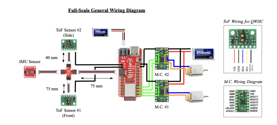
- Pin Configuration: The first motor driver is connected to Pins 9 and 10, and the second motor controller is connected to 11 and 12. These pins are selected since all of these digital pins have PWM capabilities, which are required for usage during the lab. On the motor controllers, channels A1 and B1 are tied together (in addition to A2 and B2) to increase the total current output to the stunt car motors to 4 A at the peak.
- Battery Configuration: Considering motor controllers require significant current for proper operation, the motors are powered from a separate battery as opposed to the microcontroller to prevent damage. As such, the main circuit is powered with the 750 mAh battery and the two motor controllers are connected in parallel to a 3.7 V, 850 mAh battery. This battery meets the specification of the DRV8833 dual motor driver datasheet, which requires input voltage from 2.7 V to 10.8 V
Lab #4 Outcomes
Oscilloscope Testing of PWM Signals
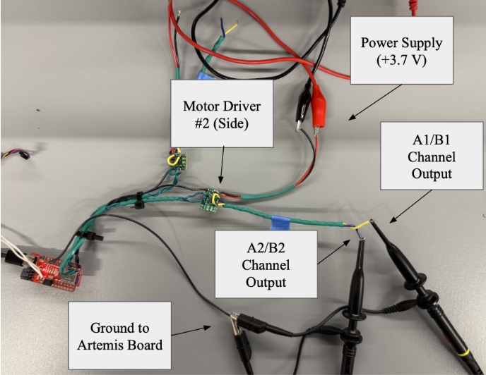
The following is the configuration for testing the respective PWM output on the applicable pins. For this example, all pins are set to 50% duty cycle, and motor controllers are probed at the end of the A2/B2 wires (grounded to the Artemis board). These initial tests are conducted with a power supply at 3.7V and a 2 A current limit for the motor controller.
Video of 50% PWM Signals
50% Duty Cycle on All Pins Code
const int Pin9 = 9; // Pint 9 for A1/B1 (M1)
const int Pin10 = 10; // Pint 10 for A2/B2 (M1)
const int Pin11 = 11; // Pint 11 for A2/B2 (M2)
const int Pin12 = 12; // Pint 12 for A1/B1 (M2)

void setup() {
 pinMode(Pin9, OUTPUT);
 pinMode(Pin10, OUTPUT);
 pinMode(Pin11, OUTPUT);
 pinMode(Pin12, OUTPUT);
 analogWrite(Pin9,0);
 analogWrite(Pin10,0);
 analogWrite(Pin11,0);
 analogWrite(Pin12,0);
}

void loop() {
 analogWrite(Pin9,128);
 analogWrite(Pin10,128);
 analogWrite(Pin11,128);
 analogWrite(Pin12,128);
}
Note: Photos of the PWM testing demonstrate slightly undeveloped square waves, indicative of issues with sampling from the oscilloscope. This was confirmed by connecting the probes directly to the pins responsible for outputting perfectly square PWM signals. Videos illustrate the first scenario to clearly show the wiring system for this set-up
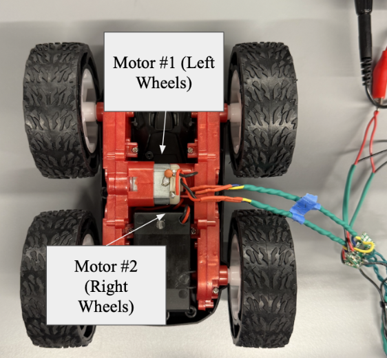
Wheel Spinning Tests with Battery and Power Supply
Video of Spinning Wheels (Power Supply)
Video of Spinning Wheels (Battery Powered)
Code for Spinning Wheels (Wheel #2 Commented Out)
const int Pin9 = 9; // Pint 9 for A1/B1 (M1)
const int Pin10 = 10; // Pint 10 for A2/B2 (M1)
const int Pin11 = 11; // Pint 11 for A2/B2 (M2)
const int Pin12 = 12; // Pint 12 for A1/B1 (M2)
...
void loop() {
 analogWrite(Pin9,125);
 //analogWrite(Pin12,75);
 analogWrite(Pin10,0);
 //analogWrite(Pin11,0);
 delay(5000);
 analogWrite(Pin9,0);
 //analogWrite(Pin12,0);
 delay(1000);
 analogWrite(Pin10, 125);
 //analogWrite(Pin11, 75);
 delay(5000);
 analogWrite(Pin10, 0);
 //analogWrite(Pin11, 0);
}
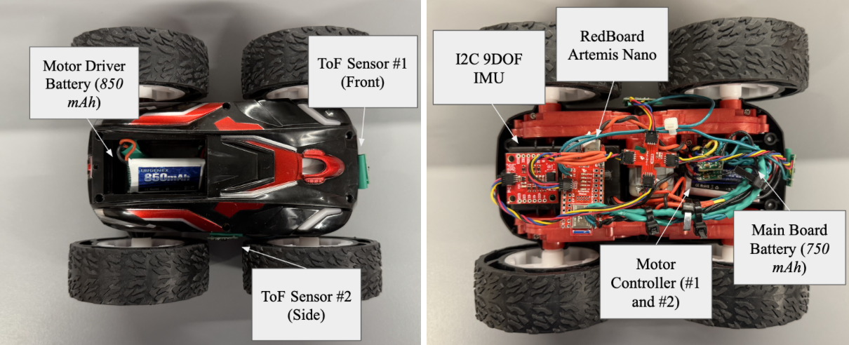
Finalized Car with Assembled Components
In order to test the efficacy of the fully assembled stunt car, a script was created that moves the car forward in intervals. Originally, the testing script was created to move the car back and forward, however, this revealed an issue with motor controller #2 moving backwards. This required altering some pin configurations temporarily to confirm viability.
Video of Independent Stunt Car Test #1
Pulse Forward Motion Code
void loop() {
 analogWrite(Pin9,125);
 analogWrite(Pin11,125);
 analogWrite(Pin10,0);
 analogWrite(Pin12,0);
 delay(500);
 analogWrite(Pin9,0);
 analogWrite(Pin11,0);
 delay(500);
}
PWM Lower Limit Experiment
The pulse forward motion code was continuously run with different “analogWrite” values to determine the minimum PWM required for effective usage. Throughout the previous examples, PWM at about ~30% duty cycle proved effective at strong motor motion, indicating a value around 30% will be ideal. The following varieties of PWM were experimented to determine an motors minimum:
- PWM ~15% (“analogWrite(38)”): Low Motor Noises and No Motion
- PWM ~20% (“analogWrite(51)”): Low Motor Noises and No Motion
- PWM ~25% (“analogWrite(65)”): Slight Staggering in Motion
- PWM ~30% (“analogWrite(77)”): Consistent Linear Motion
Calibration Factor
As seen in the previous videos, the right motor is slightly stronger (higher in torque) than the left motor. A calibration factor is added to the PWM of the left motor of 1.1 in order to account for this slight difference. This additional change creates clear linear motion, as shown in the following clips:
Video of Uncalibrated Linear Motion
Video of Calibrated Linear Motion
Calibration Factor Integration Code
float CF_Left = 1.2;
float CF_Right = 1.0;
…
void loop() {
 analogWrite(Pin9, 200*CF_Left);
 analogWrite(Pin11, 200*CF_Right);
 analogWrite(Pin13, 0*CF_Left);
 analogWrite(Pin12, 0*CF_Right);
}
Open Loop Operation
As a more complicated open-loop system, the stunt car is programmed to move forward, stop, and perform a turn during the active time. This continues indefinitely until the device is powered off. Since this has no inputs from the sensing components, this would constitute an open-loop control system. Here is a video and code of this mechanism:
Video of Open-Loop Motion
Open-Loop Turning Code
void loop() {
  // Forward
  analogWrite(Pin9, 100*CF_Left);
  analogWrite(Pin11, 100*CF_Right);
  analogWrite(Pin13, 0*CF_Left);
  analogWrite(Pin12, 0*CF_Right);
  // Stop
  delay(1000);
  analogWrite(Pin9, 0);
  analogWrite(Pin11, 0);
  delay(1000);
  // Turn
  analogWrite(Pin9, 0);
  analogWrite(Pin11, 250*CF_Right);
  analogWrite(Pin12, 0*CF_Left);
  analogWrite(Pin13, 250*CF_Left);
  delay(1000);
}
Discussion
This lab was an exciting opportunity to begin controlling the robotic as opposed to sensing. The hands-on nature of troubleshooting the motor driver integration provided a broad understanding of control mechanisms, calibration, and integration with previous topics discussed such as wireless, battery operated control. This lab was completed with Jamison Taylor, with minor AI assistance for code debugging.