Summary Lab #12
Lab #12 is a culmination of the previous labs for both electromechanical design and software development to execute a higher‑level stunt. The inverted pendulum is a common PID‑controller project, and integrating this system into the stunt car involves leveraging previous PID labs (5/6), Kalman Filtering labs (7), and stunts. The stunt car in this lab runs a basic PID‑controlled inverted pendulum from rest at a vertical position, successfully re‑orienting itself back to equilibrium. However, minor issues prevent the system from perfectly and indefinitely maintaining equilibrium, likely due to mechanical unreliability, error thresholds, and other expected deviations. Videos and flowcharts are provided to demonstrate the workflow of the device.
Lab #12 Outcomes
Successful Inverted Pendulum Operation
Other Pendulum Operation Videos
For my inverted pendulum, I aimed to have the car start from a vertical orientation and add inputs into the system by driving the car forward. Although the drive‑forward behavior was considered, it was ultimately ruled out, as the car struggled significantly to complete a flip. Generally, this uses the pitch (roll-axis) measurement on the IMU to estimate instantaneous error and drives both wheel pairs in the appropriate direction to offset the angular displacement.
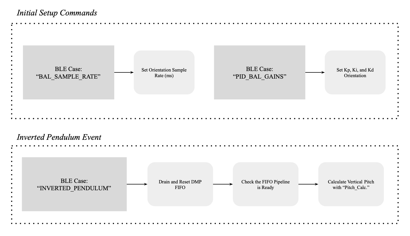
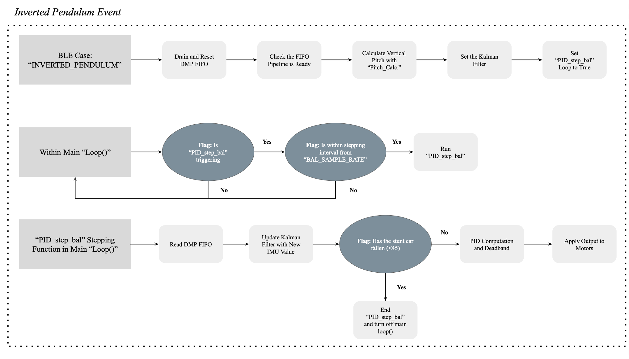
This system uses a very similar setup to previous labs, with helper functions created to store the PID values over BLE and PID inputs controlled and processed in steps within the void loop() setting. The PID controller is a closed loop with proportional, integral, and derivative gains of 20.0, 0.05, and 2.0, respectively. These were hand‑tuned through trial and error to balance effective restoration and limited overshoot. The system uses BLE commands similar to the PID linear and orientation systems from labs (5/6), with “PID_BAL_GAINS” used for setting the PID gains (Kp, Ki, Kd values), “BAL_SAMPLE_RATE” used for setting the PID stepping rate, and “INVERTED_PENDULUM” used for initiating the start of the pendulum action. More specifically for “INVERTED_PENDULUM,” the command activates a function known as “PID_step_bal()” which actually controls the stunt car reorientation.
The following are the relevant BLE commands on the Artemis:
Arduino Code (C++)
enum CommandTypes {
    ...
    INVERTED_PENDULUM,
    PID_BAL_GAINS,
    BAL_SAMPLE_RATE,
}
...
case INVERTED_PENDULUM: {
    float pitch_offset = 0.0;
    robot_cmd.get_next_value(pitch_offset);

    // Drain any stale data first
    myICM.resetFIFO();
    int warm_count = 0;
    while (warm_count < 10) {
        icm_20948_DMP_data_t warm_data;
        ICM_20948_Status_e warm_status = myICM.readDMPdataFromFIFO(&warm_data);
        if (warm_status == ICM_20948_Stat_Ok || warm_status == ICM_20948_Stat_FIFOMoreDataAvail) {
          if (warm_data.header & DMP_header_bitmap_Quat6) {
            warm_count++;
          }
        }
        delayMicroseconds(500);
    }

    pitch_calculator();
    bal_PID_target = pitch_deg + pitch_offset;
    // Seed Kalman Filter
    bal_state(0, 0) = pitch_deg;
    bal_state(1, 0) = 0.0;
    bal_sigma = {1, 0, 0, 1};

    bal_last_output  = 0.0;
    bal_integral_error = 0.0;
    bal_PID_prev_error = 0.0;
    bal_PID_last_time = millis();
    bal_start_time = millis();
    bal_PID_counter = 0;
    bal_PID_control = true;

    tx_estring_value.clear();
    tx_estring_value.append("Inverted Pendulum Started, Target: ");
    tx_estring_value.append(bal_PID_target);
    tx_estring_value.append(" deg");
    tx_characteristic_string.writeValue(tx_estring_value.c_str());
    break;
}
case END_INVERTED_PENDULUM: {
    bal_PID_control = false;
    analogWrite(Pin9,  0);
    analogWrite(Pin11, 0);
    analogWrite(Pin12, 0);
    analogWrite(Pin13, 0);
    tx_estring_value.clear();
    tx_estring_value.append("Balance Stopped");
    tx_characteristic_string.writeValue(tx_estring_value.c_str());
    break;
}

case PID_BAL_GAINS: {
    if (!(robot_cmd.get_next_value(bal_Kp)
        && robot_cmd.get_next_value(bal_Ki)
        && robot_cmd.get_next_value(bal_Kd))) return;

        tx_estring_value.clear();
        bal_integral_error = 0.0;
        bal_PID_prev_error = 0.0;
        bal_last_output = 0.0;

        tx_estring_value.append("Bal Gains: Kp=");
        tx_estring_value.append(bal_Kp);
        tx_estring_value.append(" Ki=");
        tx_estring_value.append(bal_Ki);
        tx_estring_value.append(" Kd=");
        tx_estring_value.append(bal_Kd);
        tx_characteristic_string.writeValue(tx_estring_value.c_str());
        break;
    }
Here is the definition code for the “PID_step_bal()” function, in addition to the integration into the main loop:
Arduino Code (C++)
void loop() {
    ...
    if (bal_PID_control) {
        unsigned long now = millis();
        if (now - bal_PID_last_time >= bal_PID_interval) {
            PID_step_bal();
        }
    }
}
...
void PID_step_bal() {

  unsigned long now = millis();

  float dt = (now - bal_PID_last_time) / 1000.0;
  if (dt <= 0) return;
  bal_PID_last_time = now;

  icm_20948_DMP_data_t data;
  ICM_20948_Status_e status;
  do {
    status = myICM.readDMPdataFromFIFO(&data);
  } while (status == ICM_20948_Stat_FIFOMoreDataAvail);

  bal_u(0, 0) = bal_last_output;
  K_Filt_bal_predict(dt);

  if (status != ICM_20948_Stat_FIFONoDataAvail) {
    if ((myICM.status == ICM_20948_Stat_Ok || myICM.status == ICM_20948_Stat_FIFOMoreDataAvail)
        && (data.header & DMP_header_bitmap_Quat6)) {
        double q1 = ((double)data.Quat6.Data.Q1) / 1073741824.0;
        double q2 = ((double)data.Quat6.Data.Q2) / 1073741824.0;
        double q3 = ((double)data.Quat6.Data.Q3) / 1073741824.0;
        double q0 = sqrt(1.0 - (q1*q1 + q2*q2 + q3*q3));
        double qw = q0, qx = q2, qy = q1, qz = -q3;
        double t0 = +2.0 * (qw * qx + qy * qz);
        double t1 = +1.0 - 2.0 * (qx * qx + qy * qy);
        float pitch_meas = (float)(atan2(t0, t1) * 180.0 / PI);

        if (fabs(pitch_meas - bal_state(0, 0)) < 30.0) {
            K_Filt_bal_update(pitch_meas);
        } else {
            bal_state = bal_mu_p;
            bal_sigma = bal_sigma_p;
        }
    } else {
      bal_state = bal_mu_p;
      bal_sigma = bal_sigma_p;
    }
  } else {
    bal_state = bal_mu_p;
    bal_sigma = bal_sigma_p;
  }

  // Use Kalman Filter
  pitch_deg = bal_state(0, 0);
  float pitch_rate = bal_state(1, 0);

  // Fall detection
  if (fabs(pitch_deg - bal_PID_target) > 45.0) {
    bal_PID_control = false;
    analogWrite(Pin9, 0);
    analogWrite(Pin11, 0);
    analogWrite(Pin12, 0);
    analogWrite(Pin13, 0);
    tx_estring_value.clear();
    tx_estring_value.append("Fallen at Pitch=");
    tx_estring_value.append(pitch_deg);
    tx_characteristic_string.writeValue(tx_estring_value.c_str());
    return;
  }

  float error = bal_PID_target - pitch_deg;
  const float INTEGRAL_ZONE = 10.0;
  if (fabs(error) < INTEGRAL_ZONE)
      bal_integral_error += error * dt;
  bal_integral_error = constrain(bal_integral_error, -50.0, 50.0);
  float d = constrain(-pitch_rate, -100.0, 100.0);
  bal_PID_prev_error = error;
  float output = bal_Kp * error + bal_Ki * bal_integral_error + bal_Kd * d;
  output = constrain(output, -255, 255);

  // Minimum PWM deadband
  const float BAL_MIN_PWM = 30.0;
  const float BAL_ERR_EPS = 0.2;
  if (fabs(output) > 0 && fabs(output) < BAL_MIN_PWM && fabs(error) > BAL_ERR_EPS)
    output = (output > 0) ? BAL_MIN_PWM : -BAL_MIN_PWM;
  if (fabs(error) <= BAL_ERR_EPS) output = 0;

  bal_last_output = output; // Remove Kalman Filter

  if (bal_PID_counter < time_package_size) {
    bal_timestamp_value[bal_PID_counter]    = now;
    bal_pitch_value[bal_PID_counter]        = pitch_deg;
    bal_motorPWM_value[bal_PID_counter]     = output;
    bal_proportional_value[bal_PID_counter] = error;
    bal_integral_value[bal_PID_counter]     = bal_integral_error;
    bal_derivative_value[bal_PID_counter]   = d;
    bal_PID_counter++;
  }
  if (output > 0) {
    analogWrite(Pin9,  (int)(output * CF_Left));
    analogWrite(Pin11, (int)(output * CF_Right));
    analogWrite(Pin12, 0);
    analogWrite(Pin13, 0);
  } else {
    float rev = -output;
    analogWrite(Pin12, (int)(rev * CF_Left));
    analogWrite(Pin13, (int)(rev * CF_Right));
    analogWrite(Pin9,  0);
    analogWrite(Pin11, 0);
  }
}
Additionally, a Kalman Filter is needed for this application. Although the IMU used for testing has generally been reliable, the sample rate sometimes lags or becomes inconsistent, which caused issues downstream in the workflow. This is further remedied by initializing and warming up the IMU at the start of “INVERSE_PENDULUM” to ensure more consistent data acquisition at the beginning of the robot function. The following is the Kalman Filter integrated for this use case:
Arduino Code (C++)
BLA::Matrix<2,1> bal_state   = {0, 0};  // [pitch_deg, pitch_rate]
BLA::Matrix<2,2> bal_sigma   = {1, 0, 0, 1};
BLA::Matrix<2,1> bal_mu_p;
BLA::Matrix<2,2> bal_sigma_p;
BLA::Matrix<1,1> bal_u;

void K_Filt_bal_predict(float dt) {
  BLA::Matrix<2,2> Ad = {1, dt, 0, 1};
  BLA::Matrix<2,1> Bd = {0, dt};
  bal_mu_p    = Ad * bal_state + Bd * bal_u;
  bal_sigma_p = Ad * bal_sigma * ~Ad + bal_sigma_u;
}

void K_Filt_bal_update(float pitch_meas) {
  BLA::Matrix<1,2> C  = {1, 0};
  BLA::Matrix<2,2> I2 = {1, 0, 0, 1};
  BLA::Matrix<1,1> S  = C * bal_sigma_p * ~C + bal_sigma_z;
  BLA::Matrix<2,1> K  = bal_sigma_p * ~C * Inverse(S);
  float y_tilde = pitch_meas - (C * bal_mu_p)(0, 0);
  bal_state = bal_mu_p + K * y_tilde;
  bal_sigma = (I2 - K * C) * bal_sigma_p;
}
Outcome Evaluation
The robot appears to work moderately well for a short period of time. First, the PWM and PID error charts sent over from “BAL_TRANSMISSION” showed that the motor output was effective in establishing the system and reducing pitch error. This is likely the effect of the Kalman Filter, which, in addition to some improvement in IMU latency, prevented delays in balancing steps in the main loop and reduced cascading error. By observing the packets transmitted through BLE, the robot has lower latency for processing with a 10 ms stepping rate, averaging ~10.88 ms over a 10‑second interval. Additionally, with other outlier‑removal code, the IMU provides high‑accuracy data that prevents long‑term error accumulation. These trends are shown in the following graphs:
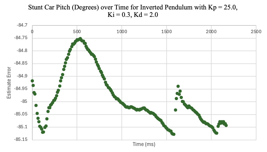
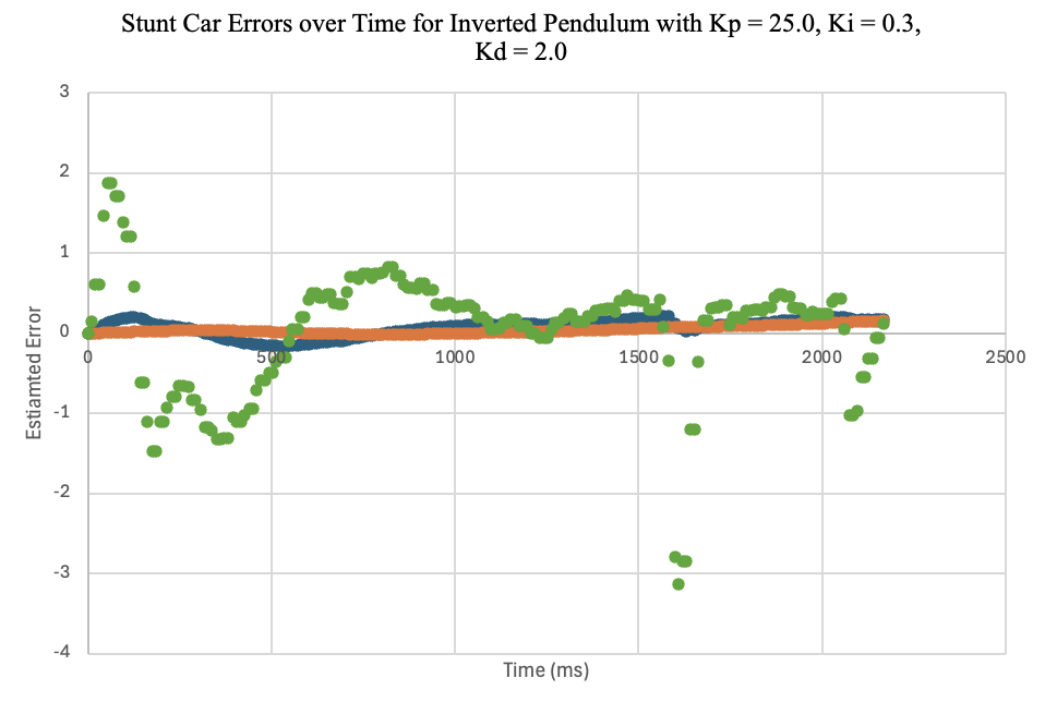
One of the major points of improvement is the PID control gains chosen for the robot. From previous trials, the robot will sometimes drift constantly without restoring or fall immediately. There are multiple reasons for this issue. The foremost reason is that the robot has an unconventional center of mass due to the addition of the 3D‑printed plate. This means the robot needs to be slightly angled (~85 degrees as opposed to 90 degrees) to maintain appropriate balance. Another reason is that the proportional and derivative gains may not be fully optimized, though they have been tuned by hand as effectively as possible. While the system restored moderately well, the car does aggressively readjust, which sometimes causes large error. Additional trials were run to confirm that this combination of proportional and derivative gains was optimal. Changing the proportional gain prevented the car from effectively re‑orienting and led to perpetual drift. Changing the derivative gain resulted in aggressive oscillations with higher amplitudes during settling. In the future, more mathematical approaches could be used to improve the outcomes. The following are some examples of “unsuccessful” trials during tuning:
Failed Trial (With PID values of 7.5, 0.05, 2.0)
Failed Trial (With PID values of 20, 0.05, 1.5)
Discussion
Overall, the system performed reasonably accurately in maintaining the designated pitch, though with some unreliability. Despite issues in previous labs with PID controllers, additional filters for random and excessive spikes and reconfigurations to the Kalman Filter significantly improved the performance of the script. Unreliability stemmed specifically from environmental and mechanical factors on the stunt car. The surface the stunt car performed on (different tables, the ground, wood, carpet, etc.) impacted drift due to varying levels of wheel slip. Throughout the lab, the stunt car was intentionally run on lab benches to standardize testing, but typically performed more effectively on rougher surfaces such as concrete or carpet.
Mechanically, the car’s performance was heavily impacted by battery level and gear backlash. While the impact of the battery is self-explanatory and directly affects motor output, the gear backlash is a more recently isolated issue. Across all labs involving PID control, the stunt car has had inconsistent driving on the left wheel pair, which has required manually adjusting the compensation factor numerous times to allow the car to drive straight. Upon closer inspection, the gears on the left pair had noticeably more backlash than the right, causing the uneven driving. This would unfortunately require extensive mechanical repairs or replacement gears to fix, and is acknowledged here as a contributing factor to imperfect stabilization.
This lab was a great opportunity to bring together various electromechanical and software principles from across the semester into a single, high-impact project. Inverted pendulums are a common portfolio project, and it was valuable to work through one in the context of this class. Despite the challenges in tuning the PID gains, the system performed well on a software level with low latency and managed to remain stabilized for 10-20 second intervals. Future improvements would involve mathematically deriving ideal gains using optimal control theory and repairing the backlash issue in the left gearbox. With these changes, the stunt car would likely perform much more reliably over longer durations. This lab was completed with Jamison Taylor, with assistance from AI tools for minor debugging. Thank you to all of the course staff for your help throughout the semester, and I hope you all have a great summer!