Sumamry Lab #6
Lab #6 is an expansion of the linear Proportional-Integral-Deriative (PID) controller developed in the previous lab (Lab #5), integrating the closed-loop feedback system based on relative orientation components. By adapting the PID-based controller for wall collision control based on the stunt car’s yaw (measured with the IMU), the closed-loop system assists in maintaining consistent yaw through disturbances and offsets.
Configuration
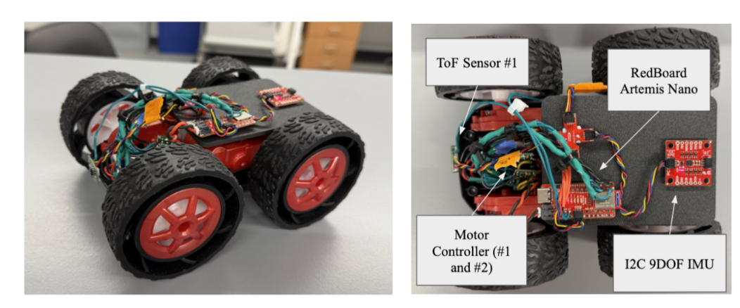
The stunt car configuration is still the same from all previous labs, including wired components, ToF locations, and overall assembly (with the 3D printed plates). Additionally, motor drivers were replaced between Lab #5 and Lab #6 due to accidental incorrect wiring for the battery. The following is an image of the stunt car and sensors for the lab:
Sending and Receiving Bluetooth for PID
A similar control format is integrated for the orientation-based PID system as the linear-based PID system. This function is natively set onto the RedBoard Artemis Nano and operates based on an on-off logic through a BLE command on the Jupyter Notebook. After this lab, PID control is split into two distinct types of control methods: linear and orientation. The previous code for wall-collision is renamed/ reworked to be labeled as the “Linear PID” and all set-up/ helper functions for this labelled “Orientation PID.” With this in mind, the following components are near-identical to the previous lab. The functions “void PID_step_ori” is initialized on the RedBoard Artemis Nano for controlling PID gain and motion with a looped step function:
Arduino Code (C++)
   while (central.connected()) {
       write_data();
       read_data();
       if(lin_PID_control){
         unsigned long now = millis();
         if(now - lin_last_PID_time >= lin_PID_interval){
           lin_last_PID_time = now;
           PID_step_lin();
         }
       }
       if(ori_PID_control){
         unsigned long now = millis();
         if(now - ori_PID_last_time >= ori_PID_interval){
           ori_PID_last_time = now;
           PID_step_ori();
         }
       }
     }
void PID_step_ori() {
   // PID Control Code to Be Added
   if (output > 0) {
       // turn right
       analogWrite(Pin9, output * CF_Left);
       analogWrite(Pin11, 0);
       analogWrite(Pin12, 0);
       analogWrite(Pin13, output * CF_Right);
   } else {
       float rev = -output;
       // turn left
       analogWrite(Pin9, 0);
       analogWrite(Pin11, rev * CF_Right);
       analogWrite(Pin12, rev * CF_Left);
       analogWrite(Pin13, 0);
   }
}
Additionally, these functions are nested into a while True loop based on the boolean value “ori_PID_control,” which altered externally from BLE, python commands “case BEGIN LIN PID,” “case END LIN PID,” and “case ORI PID GAINS:”
Arduino Code (C++)
case BEGIN_ORI_PID: {
     bool Received_input = robot_cmd.get_next_value(ori_PID_target);
     // No signal loops the previous call request
     if(!Received_input) return;
     ori_integral_error = 0.0;
     ori_PID_prev_error = 0.0;
     ori_PID_last_time = millis();
     ori_PID_counter = 0;
     ori_PID_control = true;
     // Send Data to Python Terminal
     tx_estring_value.clear();
     tx_estring_value.append("Orientation PID Started, Target Set: ");
     tx_estring_value.append(ori_PID_target);
     tx_estring_value.append(" Degrees");
     tx_characteristic_string.writeValue(tx_estring_value.c_str());
     break;
   }
   case END_ORI_PID: {
     ori_PID_control = false;
     analogWrite(Pin12, 0);
     analogWrite(Pin13, 0);
     analogWrite(Pin9, 0);
     analogWrite(Pin11, 0);
     // Send Data to Python Terminal
     tx_estring_value.clear();
     tx_estring_value.append("Orientation PID Stopped");
     tx_characteristic_string.writeValue(tx_estring_value.c_str());
     break;
   }
   case PID_ORI_GAINS: {
     bool Received_input = robot_cmd.get_next_value(Kop)
                       && robot_cmd.get_next_value(Koi)
                       && robot_cmd.get_next_value(Kod);
     if(!Received_input) return;
     // Send Data to Python Terminal
     tx_estring_value.clear();
     tx_estring_value.append("Orientation PID Gains are Set, Ori. Kp = ");
     tx_estring_value.append(Kop);
     tx_estring_value.append(", Ori. Ki = ");
     tx_estring_value.append(Koi);
     tx_estring_value.append(", Ori. Kd = ");
     tx_estring_value.append(Kod);
     tx_characteristic_string.writeValue(tx_estring_value.c_str());
     break;
   }
Jupyter Notebook (Python)
ble.send_command(CMD.PID_ORI_GAINS, "1.2|0.0|0.05")
ble.send_command(CMD.BEGIN_ORI_PID, "304")
ble.send_command(CMD.END_ORI_PID, "")
These two functions are intended for toggling the PID function on the board, and a third function “PID_ORI_TRANSMISSION” wirelessly streams time, position, and PID values for a given package size. This streaming occurs after each of the following arrays are the size of a predetermined variable saved as “time_package_size:”
Arduino Code (C++)
case PID_ORI_TRANSMISSION: {
     for (int i = 0; i < ori_PID_counter; i++) {
       tx_estring_value.clear();
       tx_estring_value.append("Time (ms): ");
       tx_estring_value.append(ori_timestamp_value[i]);
       tx_estring_value.append(",");
       tx_estring_value.append("Motor PWM: ");
       tx_estring_value.append(ori_motorPWM_value[i]);
       tx_estring_value.append(",");
       tx_estring_value.append("Distance: ");
       tx_estring_value.append(ori_distance_value[i]);
       tx_estring_value.append(",");
       tx_estring_value.append("Proportional Error: ");
       tx_estring_value.append(ori_proportional_value[i]);
       tx_estring_value.append(",");
       tx_estring_value.append("Integral Error: ");
       tx_estring_value.append(ori_integral_value[i]);
       tx_estring_value.append(",");
       tx_estring_value.append("Derivative Error: ");
       tx_estring_value.append(ori_derivative_value[i]);
       tx_characteristic_string.writeValue(tx_estring_value.c_str());
     }
     break;
   }
   case ORI_SAMPLE_RATE:{
     float new_rate_ms;
     bool Received_input = robot_cmd.get_next_value(new_rate_ms);
     if (!Received_input) return;
     ori_PID_interval = (unsigned long)new_rate_ms;
     tx_estring_value.clear();
     tx_estring_value.append("Sample rate updated to ");
     tx_estring_value.append((int)ori_PID_interval);
     tx_estring_value.append(" ms");
     tx_characteristic_string.writeValue(tx_estring_value.c_str());
     break;
   }
Jupyter Notebook (Python)
time_package_size = 5000 # Consistent with Arduino
timestamp_list = []
measurement_list = []
proportional_list = []
integral_list = []
derivative_list = []

def notif_callback_PID(UUID, Notif_Array):
    input_data = ble.bytearray_to_string(Notif_Array)
    processed_data = input_data.split(",")
    print(processed_data)
    timestamp_list.append(float(processed_data[0].split(": ")[1]))
    measurement_list.append(float(processed_data[1].split(": ")[1]))
    proportional_list.append(float(processed_data[2].split(": ")[1]))
    integral_list.append(float(processed_data[3].split(": ")[1]))
    derivative_list.append(float(processed_data[4].split(": ")[1]))
    if len(timestamp_list) >= time_package_size:
        print("Data collection complete!")

ble.start_notify(ble.uuid['RX_STRING'], notif_callback_PID)
ble.send_command(CMD.PID_ORI_TRANSMISSION, "")
Spin Test
A spin test BLE case is integrated into the RedBoard Artemis to confirm the viability of the spinning mechanisms and the battery strength of the stunt car for performing these spins. The following is the ArduinoIDE script and a video demonstrated the performance of this script:
case SPIN_TEST:{
  float start_time = millis();
    while(millis() - start_time < 500) {
      analogWrite(Pin9, 255.0);
      analogWrite(Pin11, 0);
      analogWrite(Pin12, 255.0);
      analogWrite(Pin13, 0);
    }
    analogWrite(Pin9, 0);
    analogWrite(Pin11, 0);
    analogWrite(Pin12, 0);
    analogWrite(Pin13, 0);
    tx_estring_value.clear();
    tx_estring_value.append("Spin Test Complete");
    tx_characteristic_string.writeValue(tx_estring_value.c_str());
    break;
}
Digital Motion Processing (DMP) Enabling
In addition to the previous set-up, the Digital Motion Processing (DMP) is established for the ICM-20948 9DOF breakout board to reduce drift experienced in previous labs. This is accomplished by comparing the data between the gyroscope, the accelerometer, and the magnetometer to correct error and improve the orientation measurement.
To enable the DMP, the “ICM_20948_C.h” file in the SparkFun ICM-20948 Arduino Library is edited to provide access to the DMP feature. By commenting out the “#define ICM_20948_UES_DMP” definition, the DMP feature is accessible for all future usages. “Example7_DMP_Quat6_EulerAngles” is uploaded to the RedBoard Artemis Nano to observe the improved IMU orientation measurements (pitch, roll, yaw).
Lab #6 Outcomes
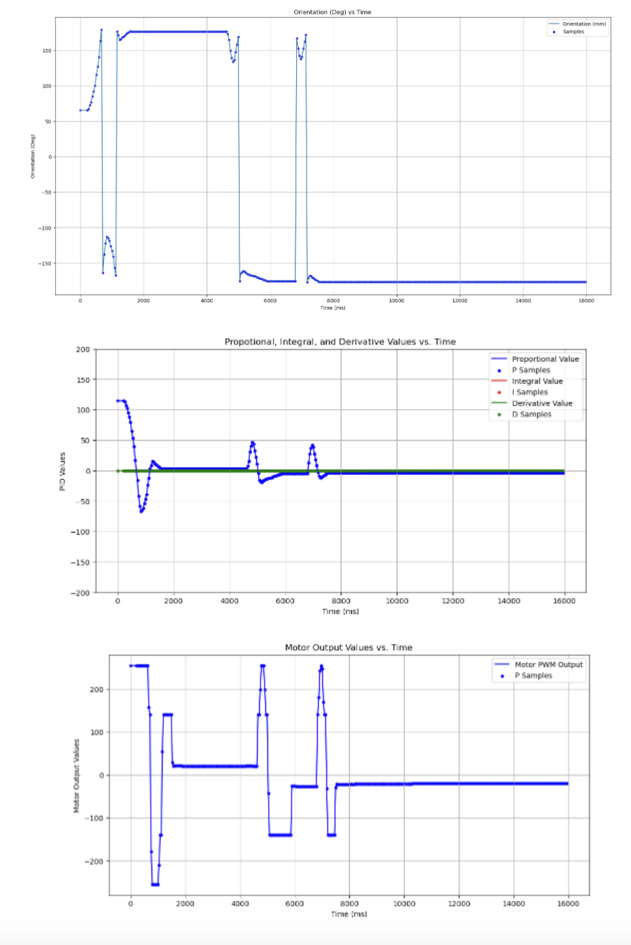
P/D Discussion
With the DMP initiated, the final closed-loop feedback controller developed for the orientation-based is a variation of the previous linear PD controller. The script receives data regarding the ideal orientation from the “PID_ORI_GAIN” function, and the main orientation controller utilizes data from the IMU to adjust the relative yaw. The PD values and response is stored locally on the Artemis Nano board, and the “PID_ORI_TRANSMISSION” function sends the data to the Jupyter Notebook script for graphing. The following are the major attributes of the orientation-based PD controller on the Artemis Nano board:
Arduino Code (C++)
void PID_step_ori() {
 unsigned long now = millis();
 float dt = (now - ori_PID_last_time) / 1000.0;
 if (dt <= 0) return;
 ori_PID_last_time = now;

 icm_20948_DMP_data_t data;
 ICM_20948_Status_e imu_status;


 // Drain FIFO until only the newest frame remains
 do {
   imu_status = myICM.readDMPdataFromFIFO(&data);
 } while (imu_status == ICM_20948_Stat_FIFOMoreDataAvail);


 // If FIFO was empty, skip this PID cycle
 if (imu_status == ICM_20948_Stat_FIFONoDataAvail) {
   return;
 }


 float yaw_deg = 0.0;
 if ((myICM.status == ICM_20948_Stat_Ok) || (myICM.status == ICM_20948_Stat_FIFOMoreDataAvail)) {
   if (data.header & DMP_header_bitmap_Quat6) {
     double q1 = ((double)data.Quat6.Data.Q1) / 1073741824.0;
     double q2 = ((double)data.Quat6.Data.Q2) / 1073741824.0;
     double q3 = ((double)data.Quat6.Data.Q3) / 1073741824.0;
     double q0 = sqrt(1.0 - (q1*q1 + q2*q2 + q3*q3));


     double qw = q0;
     double qx = q2;
     double qy = q1;
     double qz = -q3;


     double t3 = 2.0 * (qw*qz + qx*qy);
     double t4 = 1.0 - 2.0 * (qy*qy + qz*qz);
     yaw_deg = atan2(t3, t4) * 180.0 / PI;
   }
 }


 // unwrap yaw error
 float ori_proportional_error = ori_PID_target - yaw_deg;
 if (ori_proportional_error > 180) ori_proportional_error -= 360;
 if (ori_proportional_error < -180) ori_proportional_error += 360;


 // --- Derivative term (filtered) ---
 float d_raw = (ori_proportional_error - ori_PID_prev_error) / dt;
 float ori_derivative_error = ori_alpha * d_raw + (1 - ori_alpha) * ori_prev_d;
 ori_prev_d = ori_derivative_error;
 ori_PID_prev_error = ori_proportional_error;


 float output = 3 * Kop * ori_proportional_error +  Kod * ori_derivative_error; // Koi * ori_integral_error +
 output = constrain(output, -255, 255);
 const float MIN_PWM = 140;
 const float ERR_EPS = 5.0; // degrees


 if (fabs(output) > 0 && fabs(output) < MIN_PWM && fabs(ori_proportional_error) > ERR_EPS) {
   output = (output > 0) ? MIN_PWM : -MIN_PWM;
 }


 // store data
 if (ori_PID_counter < time_package_size) {
   ori_timestamp_value[ori_PID_counter] = now;
   ori_distance_value[ori_PID_counter] = yaw_deg;
   ori_motorPWM_value[ori_PID_counter] = output;
   ori_proportional_value[ori_PID_counter] = ori_proportional_error;
   //ori_integral_value[ori_PID_counter] = ori_integral_error;
   //ori_derivative_value[ori_PID_counter] = ori_derivative_error;
   ori_PID_counter++;
 }


 // symmetric turning
 if (output > 0) {
   // turn left: left reverse, right forward
   analogWrite(Pin13, output * CF_Left);  // left reverse
   analogWrite(Pin11, output * CF_Right); // right forward
   analogWrite(Pin9, 0);
   analogWrite(Pin12, 0);
 } else {
   float rev = -output;
   // turn right: left forward, right reverse
   analogWrite(Pin9, rev * CF_Left);      // left forward
   analogWrite(Pin12, rev * CF_Right);    // right reverse
   analogWrite(Pin11, 0);
   analogWrite(Pin13, 0);
 }
 if(myICM.status != ICM_20948_Stat_FIFOMoreDataAvail){
   delay(10);
 }
}
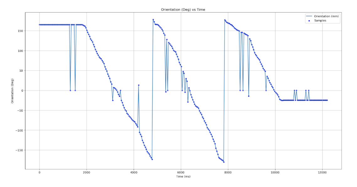
As an initial test of the IMU streaming capabilities, the motor output was hard coded to 0 and the stunt car was spun constantly to generate yaw values from -180 degrees to 180 degrees. The following is the outcome of the initial orientation test to confirm the viability of the streaming capabilities:
After confirming the strength of the motors and the streaming capabilities of the IMU through the DMP method, testing for the PID-values began. From the previous values for the linear PD, the proportional, integral, and derivative was initially set to 2.0 and 0.12, respectively.
Range and Sampling Time
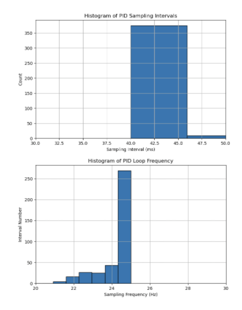
Similar to Lab #5, histograms are computed in order to determine the distribution of time sampling during the operation of the orientation PID controller (refer to previous labs for specific Jupyter Notebook scripts). The sensors are running with a message rate of ~42 ms due to bottlenecking with the availability of the DMP data, with incredibly high-variability. The following is an overview of the histogram method for comparing the sampling/ message rate:
Lab #6 Outcomes
This lab was a great chance to integrate PD knowledge from previous System Dynamics classes into real-world, robotic application. The tuning for the individual gain controllers for proportional and derivative constants provided a strong in-depth analysis for their individual contributions to motor dynamics. This lab was completed with Jamison Taylor, assisted from AI tools for minor debugging, and referenced against Tyler Wisnieski’s GitHub page for comparing effective code structures.